
New Energy Relay
Features
- 40A+ 2 poles main contacts + one set of auxiliary contacts
- Contact gap 3.6mm (main contacts)
- RT III type water-sealed relay
- Suitable for inverters, charging piles and energy storage systems for solar photovoltaic power generation

File No.:E75887

File No.:R50492936

File No.:CQC21002292050

Contact Ratings
| Contact Arrangement | 2A, 2A+1A, 2A+1B |
|---|---|
| Contact Resistance | Max.100mΩ (by voltage drop 6VDC 1A) |
| Contact Material | AgSnOIn |
| Contact Rating (Resistive) | 40A/277VAC |
| Contact Gap | 3.6mm |
| Max. Switching Voltage | 480VAC/60VDC |
| Max. Switching Current | 40A |
| Max. Switching Power | 11080VA |
| Mechanical Life | Min. 5×10⁶ OPS |
| Electrical Life | See more details at “safety approval ratings” |
Characteristics
| Insulation Resistance | 1000MΩ (at 500VDC) | |
|---|---|---|
| Dielectric Strength | Between coil & contacts | 5000VAC 1min |
| Between open contacts | 2000VAC 1min | |
| Between contacts sets | 5000VAC 1min | |
| Between auxiliary contacts | 1000VAC 1min | |
| Surge breakdown voltage (Between contact and coil) | 10000V | |
| Operate time (at nomi. volt.) | ≤30ms | |
| Release time (at nomi. volt.) | ≤10ms | |
| Humidity | 5%~85% RH | |
| Operation temperature | -40°C~+85°C | |
| UL Class F/H | Insulation System Class F/H | |
| Shock Resistance | Functional | 98m/s2 |
| Destructive | 980m/s2 | |
| Vibration resistance | 10Hz to 55Hz 1.5mm DA | |
| Unit weight | Approx. 64g | |
| Construction | Sealed Type, Flux Tight Type | |
Notes: The data shown above are initial values.
Ordering Information
| HAG02 | H | 2A | 40 | DC | 12 – | 4 | A – | S – | XXXX |
|---|---|---|---|---|---|---|---|---|---|
| Model | F or Blank:Class F H:Class H | 2A:2 Form A | 40:40A | Coil:DC | Coil Voltage | Contact Gap: Blank=Standard(3.6mm) 4=4mm | A:Auxiliary Contacts N.O. B:Auxiliary Contacts N.C. Nil:Without Auxiliary Contacts | S:Sealed Type Blank:Flux Tight Type (Vent Hole not Sealed) | Customer Code |
Notes:
1. PC board assembled with flux tight type relays can not be washed and/or coated.
2. Flux tight type relays can not be used in the environment with dust, or H2S, SO2, NO2 or similar gaseous environment etc.
Coil Data at 25°C
| Nominal Voltage VDC | Operate Voltage (Max.) VDC | Release Voltage (Min.) VDC | Coil Resistance Ω±10% | Max. Allowable Voltage VDC |
|---|---|---|---|---|
| 6 | 4.50 | 0.30 | 19.1 | 110%V of nominal coil voltage 150%V of nominal coil voltage*1 |
| 9 | 6.75 | 0.45 | 43.1 | |
| 12 | 9.00 | 0.60 | 76.6 | |
| 24 | 18.00 | 1.20 | 306.4 | |
| 48 | 36.00 | 2.40 | 1225.5 |
Notes:*1. With no more than 24 hours per time with non-consecutive voltage application time.
Coil
| Coil Power | Approx. 1880mW |
|---|
Safety Approval Ratings
| UL&CUL | Main Contacts | 40A/277VAC, Resistive, 65°C, 1×10⁴ OPS 35A/277VAC, Resistive, 85°C, 3×10⁴ OPS 32A/277VAC, Resistive, 85°C, 5×10⁴ OPS 20A/277VAC, Resistive, 85°C, 1×10⁵ OPS 20A/277VAC, Resistive, 105°C, 1×10⁴ OPS 15A/480VAC, Resistive, 85°C, 1×10⁵ OPS 80A/277VAC, Resistive, 85°C, 1×10³ OPS(Contacts in parallel) 40A/60VDC, Resistive, 50°C, 1×10⁵ OPS Making 10A Loading 40A Breaking 10A 277VAC, Resistive Load, 85°C, 5×10⁴ OPS TV-8 277VAC, 40°C, 2.5×10⁴ OPS TV-10 120VAC, 40°C, 2.5×10⁴ OPS |
|---|---|---|
| Auxiliary Contacts | 1A 30VDC, Resistive, 85°C, 1×10⁵ OPS 1A 277VAC, Resistive, 85°C, 1×10⁵ OPS | |
| TüV & CQC | Main Contacts | 40A/277VAC, Resistive, 65°C, 1×10⁴ OPS 35A/277VAC, Resistive, 85°C, 3×10⁴ OPS 32A/277VAC, Resistive, 85°C, 5×10⁴ OPS 20A/277VAC, Resistive, 85°C, 1×10⁵ OPS 20A/277VAC, Resistive, 105°C, 1×10⁴ OPS 15A/480VAC, Resistive, 85°C, 1×10⁵ OPS 80A/277VAC, Resistive, 85°C, 1×10⁴ OPS(Contacts in parallel) 40A/60VDC, Resistive, 50°C, 1×10⁵ OPS Making 10A Loading 40A Breaking 10A 277VAC, Resistive Load, 85°C, 5×10⁴ OPS |
| Auxiliary Contacts | 1A 30VDC, 85°C, 1×10⁵ OPS 1A 277VAC, 85°C, 1×10⁵ OPS |
NOTES:
1. All values without specified temperature are at 25°C.
2. The above lists the typical loads only. Other loads may be available upon request.
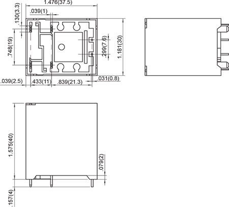
OUTLINE DIMENSIONS, WIRING DIAGRAM AND PC BOARD LAYOUT. Unit: inch(mm)
Outline Dimensions
Without Auxiliary Contact
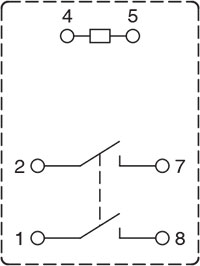
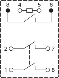
Wiring Diagram
(Bottom view)
Without Auxiliary Contact
PCB Layout
(Bottom view)
Without Auxiliary Contact
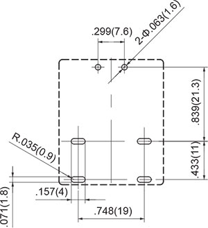
* The tolerance without indicating for PCB layout is always ±0.1mm.
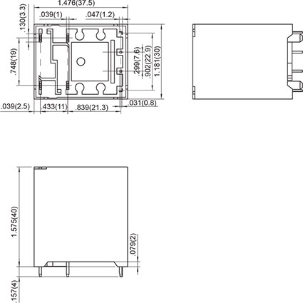
Outline Dimensions
Auxiliary Contact
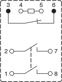
Wiring Diagram
(Bottom view)
Auxiliary Contact
N.O.

Auxiliary Contact
N.C.
PCB Layout
(Bottom view)
Auxiliary Contact
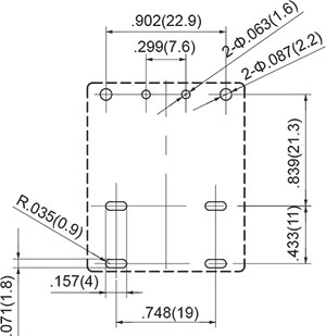
* The tolerance without indicating for PCB layout is always ±0.1mm.
Unless otherwise specified tolerances are:
| ≤1mm | >1mm and ≤5mm | >5mm |
| ±0.2mm | ±0.3mm | ±0.4mm |
PACKAGING SPECIFICATION
| BLISTER BOX | OUTER CARTON | OUTER CARTON SIZE |
|---|---|---|
| 25PCS | 100PCS | L280mm*W220mm*H230mm |
APPLICATION GUIDELINES
Automatic Wave Soldering
* Wave solder is the optimum method for soldering.
* Adjust the level of solder so that it does not overflow onto the top of the PC board.
* Unless otherwise specified, solder under the following conditions depending on the type of relay.
| Preheat time 20°C-100°C | Rising slope 20°C-120°C | Decreasing slope Peak-150°C | Slodering temperature 255°C-265°C |
|---|---|---|---|
| 90±5 seconds | <3°C/s | <4°C/s | 3~5s |
Hand Soldering
* Keep the tip of the soldering iron clean.
| Solder lron | 30W or 60W |
|---|---|
| lron Tip Temperature | Approx. 350°C 662°F |
| Solder Time | Within approx. 3 seconds |
* Immediate air cooling is recommended to prevent deterioration of the relay and surrounding parts due to soldering heat.
* Although the sealed type relay can be cleaned, avoid immersing the relay into cold liquid
(such as washing solvent) immediately after soldering. Doing so may deteriorate the sealing performance.
Discard the dropped product
![]()