
Features
- Application: telecommunication equipment, solar, construction machinery, electrical vehicle, electric forklift, train, UPS
- Heavy load capacity: 120A contact switching capacity
- Compliant UL60947-4-1 5000A SCPD test

File No.:E198243

File No.:R 50574994

Contact Ratings
| Contact Arrangement | 1A |
|---|---|
| Contact Resistance | ≤10mΩ(by voltage drop 20A 6VDC) |
| Contact Material | AgSnO |
| Contact Rating (Resistive) | 120A/305VAC, 120A/60VDC |
| Contact Gap | 3mm |
| Max. Switching Voltage | 600VAC/60VDC |
| Max. Switching Current | 120A |
| Max. Switching Power | 48000VA/7200W |
| Mechanical Life | 1×10⁵ operations |
| Electrical Life | 1×10⁴ operations |
Characteristics
| Insulation Resistance | 1000MΩ (at 500VDC) | |
|---|---|---|
| Dielectric Strength | Between coil & contacts | 5000VAC 1min (50Hz/60Hz) |
| Between open contacts | 2000VAC 1min (50Hz/60Hz) | |
| Surge Voltage (Between coil & contacts) | 10kV(1.2/50μs) | |
| Impulse Current | 400A/350VDC/4ms | |
| Operate time (at nomi. volt.) | ≤30ms | |
| Release time (at nomi. volt.) | ≤15ms | |
| Humidity | 5%~85% RH | |
| Operation temperature | -40°C~+85°C | |
| UL Class F | Insulation System Class F | |
| Shock Resistance | Functional | 98m/s2 |
| Destructive | 980m/s2 | |
| Temperature Rise | 130K Max(contact Load 120A, 110% rated current excitation, @25°C) | |
| Vibration resistance | 10Hz to 55Hz 1.5mm DA | |
| Unit weight | Approx. 165g | |
| Construction | Flux Tight Type | |
Notes: The data shown above are initial values.
Ordering Information
| HAG12 | A | DC | 24 | XXXX |
|---|---|---|---|---|
| Model | A:SPDM single-pole, double-make | Coil:DC | Coil Voltage | Customer Code |
Notes:
1. PC board assembled with flux tight type relays can not be washed and/or coated.
2. Flux tight type relays can not be used in the environment with dust, or H2S, SO2, NO2 or similar gaseous environment etc.
Coil Data at 25°C
| Nominal Voltage VDC | Operate Voltage (Max.) VDC | Release Voltage (Min.) VDC | *Max. Allowable Voltage VDC | Coil Resistance Ω±10% |
|---|---|---|---|---|
| 12 | 9.00 | 0.60 | 13.20 | 30.0 |
| 18 | 13.50 | 0.90 | 19.80 | 67.5 |
| 24 | 18.00 | 1.20 | 26.40 | 120.0 |
Note:”*Max Allowable Voltage”: The relay coil can endure max allowable voltage for a short period time only.
Coil
| Coil Power | 4.8W |
|---|
Technical Data
| Category of protection according to IEC 61810-1 | RT II | |
|---|---|---|
| Flammability class according to UL94 | V-0 | |
| Insulation material group | IIIa | |
| Pollution degree | 2 | |
| Insulation between open contacts | Type of disconnection | Full-disconnection |
| Overvoltage category | II | |
| Rated impulse voltage | 2.5kV (1.2/50 μs) | |
| Creepage distance | 11 mm | |
| Clearance distance | 3 mm | |
| Insulation between coil and contact | Type of insulation | Reinforced |
| Overvoltage category | III | |
| Rated impulse voltage | 6kV (1.2/50 μs) | |
| Creepage distance | 18.6 mm | |
| Clearance distance | 15 mm | |
Safety Approval Ratings
| Load Type | Voltage AC/DC | Current | Surrounding air Temp. | Operations | ||
| UL&CUL | Resistive load AC | 120/220/250/277/288/305/320/400/600 | AC | 80A | 85°C | 100,000 ops |
| Resistive/General load AC | 120/220/250/277/288/305 | AC | 120A | 65°C | 10,000 ops | |
| Resistive load DC | 30 | DC | 100A | 80°C | 100,000 ops | |
| Motor | 250 | AC | 5HP | 85°C | 100,000 ops | |
| TV load | 120/240 | AC | TV-20 | 85°C | 100,000 ops | |
| TüV | Resistive load AC | 120/220/250/277/288/305/320/400/600 | AC | 80A | 85°C | 30,000 ops |
| 120/220/250/277/288/305 | AC | 120A | 65°C | 10,000 ops | ||
| Resistive load DC | 30 | DC | 100A | 85°C | 100,000 ops | |
| 60 | DC | 120A | 65°C | 3,000 ops |
NOTES:
1. All values without specified temperature are at 25°C.
2. The above lists the typical loads only. Other loads may be available upon request.
OUTLINE DIMENSIONS, WIRING DIAGRAM AND PC BOARD LAYOUT. Unit: inch(mm)
Outline Dimensions

Wiring Diagram
(Bottom view)

PCB Layout
(Bottom view)

* The tolerance without indicating for PCB layout is always ±0.1mm.
Unless otherwise specified tolerances are:
| ≤1mm | >1mm and ≤5mm | >5mm |
| ±0.2mm | ±0.3mm | ±0.4mm |
PACKAGING SPECIFICATION
| BLISTER BOX | OUTER CARTON | OUTER CARTON SIZE |
|---|---|---|
| 9PCS | 54PCS | L455mm*W220mm*H185mm |
Characteristic Curves
MAXIMUM SWITCHING CURRENT OF RELAY

AMBIENT TEMPERATURE
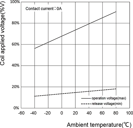
CHARACTERISTICS AND COIL APPLIED
COIL TEMPERATURE RISE

MALFUNCTION SHOCK

Shock direction
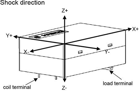
Measure the value of contact malfunction happening by applying 3 axes with 6 direction 3 times each.
PACKAGING SPECIFICATION
| BLISTER BOX | OUTER CARTON | OUTER CARTON SIZE |
| 8PCS | 48PCS | L455mm*W220mm*H185mm |
APPLICATION GUIDELINES
Automatic Wave Soldering
* Wave solder is the optimum method for soldering.
* Adjust the level of solder so that it does not overflow onto the top of the PC board.
* Unless otherwise specified, solder under the following conditions depending on the type of relay.
Lead-free tin wave soldering curve

| Preheat time 20°C-100°C | Rising slope 20°C-120°C | Decreasing slope Peak-150°C | Slodering temperature 255°C-265°C |
|---|---|---|---|
| 90±5 seconds | <3°C/s | <4°C/s | 3~5s |
Hand Soldering
* Keep the tip of the soldering iron clean.
| Solder lron | 30W or 60W |
|---|---|
| lron Tip Temperature | Approx. 350°C 662°F |
| Solder Time | Within approx. 3 seconds |
* Immediate air cooling is recommended to prevent deterioration of the relay and surrounding parts due to soldering heat.
* Although the sealed type relay can be cleaned, avoid immersing the relay into cold liquid
(such as washing solvent) immediately after soldering. Doing so may deteriorate the sealing performance.
Discard the dropped product
![]()